|
T H E
C A S T L E
R I G G
P R O J
E C T
THE CASTLE RIGG PROJECT
PETER STEWART
Submitted on behalf of the Keswick School Project Team
|
27th April, 1976 |
Keswick School,
Keswick, Cumbria. |
|
|
Peter Bestley | |
|
Peter Hodgson | |
|
Philip Johnson | |
|
Anne Seneviratne | |
|
Peter Stewart | |
|
Alan Wylie | |
|
David Wylie | |
|
Margaret Wylie |
THE CASTLE RIGG PROJECT
OBJECTIVE
The objective of the Castle Rigg project is to study the mathematics, including the geometry, of megalithic stone circles,
using computer techniques and to make deductions about their design and use.
CHOICE OF SUBJECT
This subject was chosen for study since there is a megalithic stone circle at Castle Rigg, near Keswick School
and because the project leader, a member of the lower sixth form, is interested in mathematics and in the application
of computer techniques to problem solving.
HISTORICAL REVIEW
QUANTUM
Broadbent (1955) has developed statistical methods for the investigation of a quantum hypothesis (a quantum being a fixed
unit of length) and has extended this (Broadbent 1956) to the examination of a quantum hypothesis based on a single
set of data. Thom (1962) applied these methods to his data on megalithic sites and has concluded that a standard
length, which he calls the megalithic yard (My.), is used extensively if not exclusively. These methods are considered adequate by
Porteous (1973) to exclude a rectangular hypothesis (random distribution) but are said not to differentiate between quanta based on pacing,
the pacing hypothesis, or on measuring with a standard length, the exact quantum hypothesis. It is preferred here to cite
these as the pacing hypothesis and the yardstick hypothesis respectively. Porteous (1972) exemplified his thesis with made up data and
did not produce objective evidence to support it. In the discussion which followed the paper by Thom (1955) the possibility
that the quantum was the human pace was advanced. Kendall (1955) suggested that the variance of an observed length was
of the form an + b where n is the number of paces; a is a component representing the variance
of the individual and b is a component representing the variance between individuals.
GEOMETRY
In his book "Megalithic sites in Britain" Thom (1967) has surveyed and classified many sites and further data
has been provided in a subsequent book "Megalithic Lunar Observatories" by Thom (1971). The term "stone circle" is widely used
although it has to be qualified and the shape of some is described as a flattened circle or as an
egg shaped circle. Some ellipses are also found. The geometry has been described for the flattened circles and for the
egg shaped circles (Thom 1967). At least 125 circular "circles" are known with 35 flattened circles, 9 egg shaped circles
and 9 ellipses. Castle Rigg is an example of a flattened circle and Clava is an example of an egg
shaped circle. These types were illustrated in the first report of 15.12.75.
ASTRONOMICAL ALIGNMENTS
The application of computer techniques to the analysis of all possible alignments at megalithic sites has confirmed
previously suggested alignments at Stonehenge and Callanish (Hawkins 1963,1965) and has disclosed others (Hawkins 1963). The application and value of
computer techniques in discovering the alignments of megalithic astronomy has been reviewed by Hawkins (1970). The possibility of astronomical alignments
at Castle Rigg was apparently first suggested by Morrow (1903-09) cited by Anderson (1915). It was suggested by Anderson (1915)
that the main alignment marked sunrise at an important date in the Celtic calendar.
AXIS ORIENTATION
No report has been discovered which attempts to relate axis orientation to latitude or to any other
factor. Data about axis orientation were obtained from the plans of circles published by Thom (1967)
LEY LINES
The occurrence of ley lines was described by Watkins (1925) in his book "The Old Straight Track".
He produced evidence of "the alignment across miles of country of a great number of objects, or sites of objects,
of prehistoric antiquity" and concluded that there were "straight trackways in prehistoric time in Britain". Mitchell (1969) believed in the
existence of ley lines and supported their existence with speculation and psychic revelation. The occurrence of ley lines does not
appear to have been investigated scientifically.
INVOLVEMENT OF PUPILS
The project has been carried. out by a team of eight pupils from Keswick School, Keswick, Cumbria and this
report is submitted by the project leader, Peter Stewart, on behalf of the Keswick School Project Team (ages shown): Peter
Bestley, (15); Peter Hodgson, (17); Philip Johnson, (18); Anne Seneviratne, (16); Peter Stewart, (17); Alan Wylie, (18); David Wylie, (12)
and Margaret Wylie, (16). Some assistance with data extraction was provided by John Bibby, (11). Some of the discussions which
took place prior to preparation of the earlier report were attended by Richard Smith, (15); Stephen Temple, (17) and Paul
Whittaker, (15). Following discussion with advisors the initial project was prepared. The field work, data collection and computer programming have
been carried out solely by pupils but teachers and other advisors have been consulted for astronomical, statistical and other advice.
DEVELOPMENT
Since the first report was submitted on 15.12.75 the main stages have been modified and the fourth stage
has been sub-divided into a fourth and fifth stage. Methods have been changed in the light of practical experience and
these changes are described under each stage. It has been realised that the project is extremely complex. and an attempt
has been made to modify it so that results could be obtained within a reasonable time.
DATA COLLECTION
All data have been collected solely by pupils without assistance and without supervision from teachers or advisors.
In Stage I the measurement of quanta by pace and stick has been done by a team of 2-5 pupils,
usually 3 or 4. In Stage II the survey of Castle Rigg was completed after several preliminary surveys, each involving
at least 4 pupils, and all pupils have taken part in the survey at some stage. In Stage II co-ordinate
data from published circles have been extracted by 4 pupils. It is intended that each set of data extracted by
one pupil should be checked by another. In Stage III the survey of Castle Rigg to obtain stone and horizon
altitude measurement has been carried out by a team of 3 or 4 pupils. In Stage IV data relating to
axis orientation and to latitude and longitude were taken from published circles. The data were extracted by one pupil and
were checked by another. In Stage V most of the data were extracted by one pupil from ordinance survey maps.
These data have not yet been checked.
COMPUTER PROGRAMMES
In Cumbria a Hewlett Packard 9830A calculator model 30 is available and some schools have the use
of the calculator for approximately six weeks in each year. The calculator was available to Keswick School from late February
until April, 1976. Programmes have been written in BASIC language and some development work for the project has been carried
out. The programming and development work has been carried out solely by Peter Stewart and Alan Wylie without assistance and
without supervision. Programmes for Stage I and Stage II were written by Peter Stewart and for Stage III by Alan
Wylie. The programme for Stage V was written in part by Peter Stewart and in part by Alan Wylie. A
series of small programmes to load, reload, correct, list or store data were written by Peter Stewart or Alan Wylie.
All programmes have been jointly developed.
LIBRARY WORK
The Librarian at Keswick Public Library, Mr. Elsby, kindly supplied a list of references relating to Castle
Rigg in the Transactions of the Cumberland and Westmorland Antiquarian and Archaeological Society. These have been studied and some other
references have been found.
Dymond (1880) gave an accurate plan of Castle Rigg circle and cited a reference that there was "a second
circle in the field nearer to Keswick". There is, however, no record of the position of this circle. Anderson (1915)
also gave a plan of Castle Rigg and cited Morrow (1908-09) as being the first to associate alignments with Castle
Rigg, both astronomical and geographical, the latter being an alignment with Great Mell Fell. Anderson (1915)* stated that a second
outlier was known at one time and considered that the main outlier (now the only one) and the centre of
the circle were aligned with Fiends Fell in the Pennines. This was said to mark the sight of sunrise on
or about the 1st May, the time of the Bealtuinn feast, an important data in the Celtic calendar. Long Meg
and her daughters and Little Meg are said to indicate the same alignment. Anderson (1923 B) reported that the outlier
now standing had been moved when a new road was built and that it had plough marks on it indicating
that it had Fallen and had since been re-erected. A claim of Thom (1967) that this outlier makes Castle Rigg
one of the most important stone circles must, therefore, be regarded with caution. Anderson (1923C) found a tumulus on Great
Mell Fell which is circular but with one gap in the circle. This gap aligns exactly with Castle Rigg.
References have been found to other stone circles in Cumbria. All those with plans have been examined and the
co-ordinates of each stone have been determined from these plans on superimposed tracing graph paper. A list of circles from
which data were extracted in this way are given in Table 1. The plan of Castle Rigg by Dymond (1880)
was not used because the binding makes it impossible to extract data accurately.
Standard texts on statistics (Spiegel, 1972) and on astronomy (Smart, 1942) were used for reference.
* See library work addendum page 5
CASTLE RIGG SITE
Further examination of the site has shown that the line of buried stones referred to in
the first report of 15.12.75 is not on the meridian, although it is fairly close to it, and probably marks
the line of an old wall. It is believed that the site of the second circle has now been located.
A tumulus has been found with surrounding circular earthwork and close by are many large stones, possibly displaced from the
circle. The tumulus, the outlier and the centre of Castle Rigg circle appear to be in a straight line and
the outlier is approximately equidistant from both. It is hoped that an aerial photograph can be obtained and that it
will provide verification of this.
OTHER CUMBRIAN CIRCLES
Other circles in Cumbria have been visited including Long Meg, Little Meg, Little Salkeld, Sunkenkirk, Burnmoor,
Elva Plain and Seascale. The cup and ring marks noted by Dymond (1913) to be present on Long Meg and
Little Meg were seen and photographed. Seascale was regarded with particular interest because Thom (1967) had not been able to
classify it. It is hoped to survey and to analyse it when the analysis programme is working. It consists of
10 stones, all upright, and seemingly well preserved. The good state of preservation raised some doubts as to its authenticity
and this was strengthened by the ordinance survey map which describes it as "stone circle, site of". Subsequently the report
by Fletcher (1958) was found relating to Seascale stone circle. It was re-erected in 1957 by pupils from Pelham House
School and data have been extracted from the plan reported by Fletcher (1958). The re-erection might explain the difficulty which
Thom (1967) had in classifying it. Objective analysis of this circle would clearly be of great interest.
Photographs have been taken of a number of circles and of interesting features. These should be available in May,
1976.
ADJUDICATION 25TH MAY, 1976
It is noted that adjudication will take place in London on Tuesday, 25th May, 1976.
Unfortunately two members of the team, Philip Johnson and Alan Wylie will not be able to attend because they have
'A' level examinations on this date. Alan Wylie had contributed particularly to the computer programming, having been solely responsible for
the Stage III programme.
Description of the method used for data collection for Stage I will be presented by Peter Bestley.
Extraction of co-ordinates from published stone circles in Stage II will be described by Anne Seneviratne.
The surveying methods for stone circles used in Stages II and III will be presented by Peter Hodgson.
The investigation of axis orientation from published circles and correlation with latitude in Stage IV will be presented by
Margaret Wylie.
In Stage V the extraction of data relating to ancient sites in Cumbria will be presented by David Wylie.
All questions relating to computer programmes will be dealt with by Peter Stewart.
LIBRARY WORK ADDENDUM
The paper by Morrow J., (1908), Proceedings of the University of Durham Philosophical Society iii, 71 has now been
obtained. It makes no reference to a second outlier and the statement that there was a second outlier appears to
be based on a mis-reading, by Anderson (1915) of the paper by Morrow (1908).
STAGE I: QUANTUM DETERMINATION
INTRODUCTION
In megalithic times circles may have been measured by means of a yardstick (Thom 1955) or by pacing
(Kendall 1955). The pacing hypothesis was favoured by Porteous (1973) who used made up data for paces which had an
arbitrarily chosen mean and standard deviation. The main purpose of this stage of the project was to repeat the calculation
of Porteous (1973) using real data instead of made up data. It was intended to calculate the mean pace and
standard deviation not only for each individual but also to compare one step with another and thus to provide information
about variation for each individual and between individuals. The performance of thirty volunteers at Keswick School are being measured in
respect of comfortable paces: The Keswick Pace; in respect of paces made to simulate the megalithic yard: the Keswick Yard
and in respect of measurements made with a stick to simulate the megalithic yard: the Keswick Stick. At the time
of writing data have been collected from 14 subjects. Data are also being collected from each subject in respect of
age, sex, standing height wearing shoes and of sitting height. It is intended to seek correlation between these parameters and
the pace and stick measurements.
THE KESWICK PACE
Each subject was asked to take five comfortable paces, neither overstretched nor understepped, in a sand
pit. The first pace was taken from a reference board. The subject was free to start with either foot but
the starting foot, left or right, was noted. A plastic marker tag was placed in the sand to indicate the
limit of the heel print of each step. The position of each marker was agreed by two independent observers. The
horizontal distance of each pace from the reference point was measured by two independent observers and, when agreement was reached
the distance was recorded. The experiment was repeated with a further five paces but with the first step being taken
by the opposite foot.
THE KESWICK YARD
After completion of the experiment to measure 10 Keswick Paces the subject was asked to adjust
his or her paces to be equal, as nearly as possible to the megalithic yard. A practise area approximately 100
yards away from the sand pit was marked out in megalithic yards and the subject was allowed to practise for
about five or ten minutes while other subjects were being measured. The subject then returned to the sand pit and
took five paces, starting with the same foot as was used for the first set of 5 Keswick Paces. The
paces were measured and recorded. After an interval of about five minutes, during which time further practise was not allowed,
the experiment was repeated starting with the opposite foot.
THE KESWICK STICK
Each subject was given a cane stick and a measure cut to the length (829 mm)
of the megalithic yard. The subject was asked to mark on the stick the length of the megalithic yard, or
if preferred to cut the stick to the length of a megalithic yard. The subject was then asked to mark
out five megalithic yards on the ground starting with one end of the stick against the reference point. When the
stick had been placed on the ground to record the second yard a plastic marker tag was placed at the
end nearest to the start to indicate the end of the first yard. The Horizontal distance from the start to
she first and to each subsequent marker was agreed by two independent observers and was recorded.
HORIZONTAL MEASUREMENTS
Particular care was taken to ensure that accurate measurements were obtained of the horizontal distance between paces
or stick measurements. A reference board was used for all paces and measurements. Two metal tape measures were placed approximately
three foot apart, parallel to each other at right angles to the reference board and along each side of the
sand pit. A loop at the end of each tape was hooked over a metal screw fixed to the reference
board. The first step commenced from a wooden block about 6 cm from the screws and this distance, called the
end correction, has to be subtracted from the first marker point to give the measurement of the first pace. A
straight cross piece was placed so that it exactly touches the edge of a plastic marker. The cross piece must
be parallel to the reference board and this was ensured if the edge of the cross piece was lying on
each tape measure at an equal distance from the screws. At least two observers were involved in the measurements and
in some instances results were more quickly obtained with up to five observers. One observer for each tape measure ensured
that the cross piece was at the same position on each tape measure. When agreement was reached, the measurement was
recorded.
SUBJECT DATA
For each subject age and sex was recorded together with measurements of standing height wearing shoes and
of sitting height. In each instance the measurement was agreed by two independent observers before it was recorded.
COMPUTER PROGRAMME OUTLINE
The input data consisted of measurements taken from the end of the tapes at each step. The actual length
of each step was obtained by subtraction of adjacent measurements and the length of each step was stored. For all
thirty subjects a mean length and standard deviation will be obtained for each of five steps, starting with the left
foot and for a similar set starting with the right foot. To calculate the significance of different means the Z
statistic is calculated. It is intended that a comparison should be made firstly of steps taken with the left foot
and of the right foot, secondly of all the paces taken by each of thirty subjects and thirdly of the
first step with subsequent steps. The mean pace size for different subjects will be compared with age, sex, height, sitting
height and leg length. Possible correlation between different groups will be tested by calculating the least squares, regression line and
the coefficient of correlation. It is expected that the correlation will be found between the mean pace of different subjects
with age and leg length.
Data in respect of the Keswick Yard and the Keswick Stick will be investigated in the same way as
the Keswick Pace. The correlation coefficient in respect of the Keswick Yard should show to what extent subjects can overcome
factors such as leg length which may determine the natural step size. No correlation is expected between the Keswick Stick
and the factors which may be correlated with paces.
To establish the existence of a quantum, the Criterion C of Broadbent (1956) will be calculated. A convenient method
of doing this is described by Thom (1967). The Criterion C will be estimated for the Keswick Pace and the
Keswick Stick to see which best fits the hypotheses suggested by Thom (1955) with respect to the megalithic yard and
Kendall (1955) with respect to the pace.
RESULTS
A computer programme has been written to carry out a preliminary analysis of 14 sets of data presently
available. The computer programme, data and results are given. A list of variables used is given in the appendix. It
is obvious that the data have not been correctly recorded for Subject 12, column 1 and the measurements for this
subject will have to be repeated.
CONCLUSION
The preliminary results obtained for analysis in respect of 14 subjects are of considerable interest. Several tentative conclusions
may be drawn but are advanced with caution, until such time as all data have been obtained and analysed.
1. In the Keswick Yard the first stride is significantly shorter than the fifth stride and there is a
tendency for successive strides to become progressively longer, at least as far as the fifth stride. It would appear that
the formula proposed by Kendall (1955) may require modification.
2. The Keswick Stick is much more accurate than the Keswick Pace or the Keswick Yard as is indicated
by the much smaller standard deviation of the former.
3. The Keswick Yard at 86.32 cm ±6.74 or 33.98 inches ±2.655 has a standard deviation which is much
bigger than that arbitrarily chosen by Porteous (1973) at 33 inches ± 0.5. This suggests that the pace hypothesis is
a much weaker contender than Porteous believed.
4. The preliminary analysis strongly supports the existence of a megalithic yard as suggested by Thom (1955).
STAGE II: GEOMETRICAL ANALYSIS
In this stage methods have been developed to classify objectively different types of stone ring known. Objective analysis would be
particularly useful in
the examination of difficult circles which have not previously been classified. It would also lead to more accurate determination of
the circle centre and hence would provide more accurate information for investigation of megalithic yard measurements. There are four main
geometrical types of stone ring: circle, flattened ring, egg shaped ring and ellipse. In the cases of the circle there
is one construction point, the centre, and in the case of the ellipse there are two points, the foci. In
the case of the flattened and the egg shaped rings there are several construction points from which auxiliary arcs are
drawn but in both the flattened and the egg shaped ring there is a main centre from which an arc
of at least 180° is derived. Determination of this main arc centre is of prime importance in all rings (for
an ellipse this point would be the centroid) for the shape can be specified with reference to this point. In
all cases classification involves determination of the centroid, the main arc centre, the long axis and the short axis. The
problem has turned out to be much more complex than had been anticipated but it is believed that a solution
can be found and an objective method of classification is being developed.
COLLECTION OF DATA
Data were obtained in two ways. Firstly from a survey of the site carried out by
pupils and secondly from published plans of the various sites.
SURVEY OF CASTLE RIGG
The method used has been modified in the light of experience. It has also been
discovered that the theodolite used is accurate only to above five minutes of arc. Measurements are now being taken as
polar co-ordinates. The theodolite was placed over the estimated centre of the circle and was first sighted on the cairn
on top of Skiddaw Little Man, a prominent local land mark. Measurements were then taken on each stone, marked by
a thin rod set up at its highest point. The final reading was taken on Skiddaw Little Man cairn and
the data was accepted if this reading was the same as the original one. It is desirable that such measurements
should be checked by a second independent observer but this has not yet been done. The distance on the ground
from underneath the theodolite to the left and right edges of each stone (that is tangential measurements) at its base
was made and agreed by two independent observers. The distance from the reference point to the centre of each stone
was taken to be the arithmetic mean of the two tangential measurements.
To simplify the project it is intended to restrict measurements in the vertical (Z) axis to that of the
skyline above each stone. The photographic method would be satisfactory but is extremely time-consuming and has only recently been abandoned.
Measurements will have to be made when there is a suitable clear day. It is expected to complete the data
early in May.
PUBLISHED DATA
Data were extracted from published plans of eight Cumbrian circles (Table 1) and will be extracted from
other circles of geometric interest and from plans published by Thom (1967) and others. Tracing graph paper is placed over
the published plan. The centre of each stone and its reference number are marked and the Cartesian co-ordinates are read
off.
PROPOSED METHOD
The method is first explained in outline. Three complete rings, circle, flat and egg, each having the
main arc centre o are shown superimposed, (Figure 1). The distance from the centre to points on the circumference may
be calculated. It is obvious that the distances from the main arc centre to the main arc circumference is average
for the circle, below average for the egg and above average for the flat. A profile from point A on
the circumference clockwise through 360° defines the shape of each figure which is scaled such that the main arc radius
= 100. The profiles are also shown in Figure 1 for the circle, the flat and the egg. The line
AB is the long axis of the egg and the short axis of the flat. The line CD is the
short axis of the egg and the long axis of the flat. These axes define the primary quadrants AOC, COB,
BOD and DOA. The lines EF and GH are the perpendicular bisectors of the main axis. They define the secondary
quadrants EOG, GOF, FOH, and HOE. The characteristics of each figure may then be specified in respect of the mean
distance of points (or stones) on the perimeter from the main arc centre. The scaled radius of 100 is accepted
as standard.
1. Circle. All eight quadrants are standard.
2. Ellipse. The four primary quadrants are equal (and may or may not be standard) but the four secondary
quadrants are not. Opposite quadrants in the long axis are above standard and in the short axis are below standard.
3. Flat. Adjacent primary quadrants on one side of the long axis are standard and on the other side
are below standard. Secondary quadrants at opposite ends of the short axis are respectively standard and substantially below standard. Secondary
quadrants at opposite ends of the long axis are equal and slightly below standard.
4. Egg. Adjacent primary quadrants on one side of the short axis are standard and on the other side
are above standard. Secondary quadrants at opposite ends of the long axis are respectively standard and substantially above standard. Secondary
quadrants at opposite ends of the short ends are equal and slightly above standard.
Determination of the main arc centre requires a complex set of calculations. In preliminary studies two alternative methods were
considered but were rejected because they were not entirely suitable. The centroid may be used to give a first approximation
to the main arc centre and the mean distance (M) from the stone to the centroid is calculated. The centroid
and the mean calculated in his way should give fairly good results for a circle and ellipse but for an
egg shaped ring the centroid is displaced towards the pointed end and in the flattened ring it is displaced away
from the flattened side. This method has an important disadvantage in that correction cannot be made for displaced stones and
a very misleading position would be given by an incomplete ring. Similar but less serious objections apply to the use
of the least squares technique. This may yet, however, be used with an adaptation for the rejection of deviant stones.
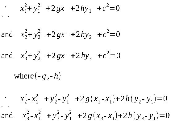
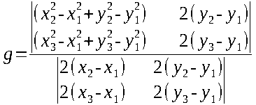
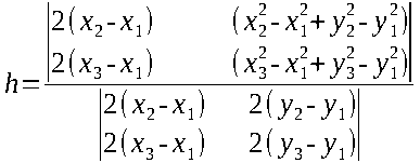
It was decided to develop a technique based on determination of a circle centre given a chord of three points.
For each set of three adjacent stones an arc centre was determined. No arc centre should lie outside the circle
and any centre which lay more than 1.5 times the mean distance (M) of perimeter stones from the centroid was
rejected. This step is necessary to reject data from misplaced stones and from stones which lie in a straight line,
for these would give an arc centre at infinity. In some types of egg shaped rings a small segment of
the perimeter does consist of stones in a straight line. The centroid of the remaining arc centres was determined and
distances from this centroid to all stones was calculated. The mean distance (D) was determined and the stone which was
most deviant from this mean was eliminated. The cycle of elimination of the most deviant stone is repeated until three
stones remain. It is anticipated that the method will first of all eliminate fallen stones which are more likely to
be misplaced than standing stones. The three stones which remain lie on the arc which gives the best estimate of
the main arc centre. From this centre the position of perfect rings, circular, flat and egg are predicted and the
positions of observed stones are measured. In Figure l stones K and R are at distance d1 (d1 = OK)
and d2 (d2 = OR) from U. OJKLM is a radius through K and OPQRS is a radius through R.
Points L and Q are on the circle circumference at standard distance from O (100 = OL = OQ). The
deviation (E) of stone K from the circle circumference is given by Ek = (d1-100) and the deviation of stone
R is similarly given by Er = (d2-100). It would be noted that E is positive, as for stone R,
if it is outside the circle and is negative as for stone K, if it is inside. Predicted values for
the deviation in respect of the flat ring are given by (OJ-OL) for stone K and (OP-OQ) for stone R.
A method for calculating J and P the predicted ideal positions on the circumference of a flat ring will be
developed later. Similarly for an egg shaped ring the deviations are given by (OM-OL) for stone K and (OS-OQ) for
stone R. Calculation of the predicted points on the circumference are expressed as an observed and as an expected deviation
from a true circle in which the deviation of each stone should be zero. The data may be printed out
in graphical form. Observed and expected data may also be examined statistically for goodness of fit with one or other
of the theoretical types of stone ring.
PRELIMINARY RESULTS
A programme has been written for the first part of the geometrical analysis and a copy of
this programme is given together with data, results and variables used. It must be emphasised that the results are not
yet satisfactory and are presented merely to indicate the potential of the method. A long and complex programme will be
required and the use of a computer would be necessary for its development.
CONCLUSION
It is concluded that objective analysis of stone circle is possible. A method of doing this is outlined.
STAGE III: ASTRONOMICAL ALIGNMENTS
It has already been mentioned that this stage has been simplified, in order that the
project might be completed in a reasonable time. It is intended that all possible alignments from the centre of the
circle at Castle Rigg to points on the horizon over each stone should be determined. They should be correlated with
the positions of the sun and moon and bright stars related to the period 2000 B.C. to 1600 B.C. At
the present time sun, moon and bright star positions are given in astronomical tables. These figures must be corrected for
the latitude of Castle Rigg and this is done using a standard formula of spherical trigonometry:
sin δ = sin Φ sin h + cos Φ cos h cos Az
where
δ = declination,
h= horizon altitude (true)
Φ = latitude,
Az = azimuth.
Correction to the years 2000 B.C. to 1600 B.C. could be obtained using De-Sitter's formula but it has been
discovered that the accuracy obtainable with the present theodolite does not warrant this correction.
Correction for refraction and temperature is important for points near the horizon but for a mountainous skyline, as it
is in Keswick, this is not necessary. Alignments from the centre are determined by calculating the equation for a line
joining two points, one of which is the centre (XoYoZo) and the other, the skyline above a stone (X1Y1Z1) as
viewed from the centre of the circle. Alignments which fall within a chosen margin of error (for example 1° of
arc) would be calculated and displayed in the printout.
RESULTS
A preliminary programme has been written but has not yet been run or tested. It does, however, indicate
some sub-routines and a format which might be used and a copy of provided.
STAGE IV: AXIS ORIENTATION
In this stage of the investigation published data on stone circles have been examined for
correlation between axis orientation and latitude. All circles published by Thom (1967) have been examined and data extracted in respect
of latitude and axis orientation. The data have been plotted and do not appear to be correlated. This is confirmed
by calculating the correlation co-efficient, which is not significant. It is intended that the correlation co-efficient should be worked out
by computer and that other factors including longitude should also be examined. In plotting the circle data it was noted
that many were in hilly areas and a search for possible correlation with height above sea level would be of
interest. It might be that many circles have been destroyed by agricultural needs and that fields in arable areas have
been cleared for this purpose.
STAGE V: LEY LINES
The claim of Watkins (1925) that there is a widespread network of leys or Lines linking up ancient sites
dues not appear to have been investigated objectively.
DATA COLLECTION
The one inch ordinance survey map of Cumbria was scrutinised and features of prehistoric interest were marked.
There were found 89 sites in all: twelve stone circles, coded as type 1; two cairn circles, coded as type
2; forty-one cairns, coded as type 3 (it should be noted that only cairns indicated by gothic type are included);
three settlements, coded as type 4; twenty-three tumuli, coded as type 5, and eight enclosures or other types of ancient
site, coded as type 6. The national grid co-ordinates were estimated for each site and information was tabulated as follows:-
1. Reference number.
2. National grid co-ordinate in X axis.
3. National grid co-ordinate on Y axis.
4. Code type of each site.
Cumbria is covered by national grid squares NX, NY, SC, SD and the reference letters are coded by means
of an additional figure in the X and Y axes (NY = 1,000X and 1,000Y, NX = 1,000Y, SD =
1,000X). Thus Castle Rigg which is situated on sheet NY at national grid reference 293/237 is recorded as having an
X co-ordinate of 1293 and a Y co-ordinate of 1237. The national grid co-ordinate of the reference cairn on Skiddaw
Little Man is NY 267/279. Examples of typical sites all from sheet NY, are identified in table II to facilitate
checking from the ordinance survey map.
All possible combinations of three sites were considered and each set of three was regarded as a triangle having
co-ordinates (X1Y1) (X2Y2) (X3Y3). The slope of each side was than calculated (θ being the angle of inclination to grid
north). A test was first made of the Y co-ordinate. If Y1 = Y2 then θ = 90°. If not
θ is calculated from the formula:- θ = Tan-1(X1-X2)/(Y1-Y2) The Slope of all three sides θ1, θ2 and θ3 were
compared and the difference between each pair was measured, A = (θ1-θ2), B = (θ2-θ3), c = (θ1-θ3). The three
points, X1, Y1; X2, Y2; and X3, Y3 were considered to be in alignment if the slope of adjacent sides
(ABC) was not greater than l (A≤1°;B≤1°;C≤1°) Data for each set of three features in alignment were printed out. When
the programme was run originally cairns were included but a very large number of alignments were found. Cairns were then
deleted and the programme was run again with 48 sites.
The results did not appear to be different from what might be expected by chance. A programme was, therefore,
written to generate random numbers. They were inserted instead of actual X and Y co-ordinates and the programme was run
again.
RESULTS
The programme, written to determine ley line alignments, is given together with data for 89 sites. The cancellation
marks at the right hand side of the printout should be ignored. They were inserted when there was a shortage
of paper, to re-use paper and cancel a previous printout. In all 209 alignments were found and are given in
the printout. A copy of the programme to generate random numbers is also given together with a printout of results:
144 alignments were found. The actual number of 209 alignments found is not significantly different from the 144 obtained with
random numbers.
χ2= 6.04
0.025>P>0.01
CONCLUSION
Although results have been obtained with this programme it should not be regarded as final and in particular
alterations may be required to ensure that the areas covered by the actual and random generated sites are equal. Nevertheless,
tentative conclusions may be made.
1. There is no objective evidence of a network of alignments linking up ancient sites in Cumbria.
2. The first conclusion is strengthened when actual alignments are examined. For example there is an alignment which includes
Castle Rigg, site number ll, and long Rigg, site number 50. These sites are fourteen miles apart and the line
joining them passes through one of the most mountainous areas of the Lake District: between Great Gable and Scafell Pike.
It appears likely that this alignment has occurred by chance rather than by design.
3. The general conclusions stated above should not be taken to exclude the possibility of significant alignments in individual
cases. In may be for instance that the apparent alignment of Castle Rigg and Long Meg with Fiends Fell in
the Pennines is real. This possibility could he investigated at other sites when the astronomical alignments programme is working.
SUMMARY AND CONCLUSIONS
In the first stage of the project statistical data on measurement by pace or stick have been obtained. The
data strongly favour the existence of megalithic yard and the measurement of sites with a yardstick. The measurement of paces
also show a significant difference between the first and subsequent paces and indicate that a formula proposed for the variance
of paces may require revision.
In the second stage of the project preliminary studies suggest that objective classification of stone circles by computer analysis
is feasible.
In the third stage of the project a possible outline programme for part of the stage has been proposed.
In the fourth stage of the project no correlation has been found between axis orientation and latitude.
In the fifth stage of the project no objective evidence has been found for the existence of a network
of ley lines between ancient sites in Cumbria.
A C K N O W L E D G E M E N T S
Grateful acknowledgement is made to the Headmaster, Mr. J. E. Thompson, M.C., M.A., V.R.D., J.P. for providing facilities; to
Mr. A. Rothwell, B.Sc. for general advice; to Dr. Thompson Ph.D for advice on astronomy; to Mr. J. Stewart B.Sc.,
for suggesting Stage I of the investigation, for discussions of methods and for advice on the presentation of results; to
Mr. Rothwell and Mr. Stewart for organising visits to other circles in Cumbria. Thanks are due also to Mr. Elsby,
Librarian, Keswick Public Library for providing references; to Mr. K. R. Bull, Librarian, Post-Graduate Institute, Wigan for obtaining references, and
to Mrs. Pilkington for typing this paper.
TABLE 1
CUMBRIAN STONE CIRCLES
|
CIRCLE |
NUMBER OF STONES |
REFERENCE | |
Sunkenkirk (Swinside) |
54 |
Dymond (1902) | |
Long Meg |
67 |
Dymond (1913) | |
Little Meg |
10 |
Dymond (1913) | |
Elva Plain |
16 |
Anderson (1923 A) | |
Shap |
34 |
Spence (1935 | |
Lacra |
6 |
Dixon & Fell (1948) | |
Seascale |
10 |
Fletcher (1958) |
TABLE 2 INFORMATION ON SOME TYPICAL ANCIENT SITES IN CUMBRIA
|
No. |
X |
Y |
GRID |
NAME |
CODE |
TYPE | |
11 |
1293 |
1237 |
293/237 |
Castle Rigg |
1 |
Circle | |
50 |
1173 |
1027 |
173/027 |
Longrigg |
2 |
Cairn circles | |
51 |
1217 |
1015 |
217/015 |
Hardknot |
3 |
Cairn | |
55 |
1330 |
1232 |
330/242* |
Threlkeld |
4 |
Settlement | |
56 |
1398 |
1254 |
398/254 |
Great Mell Fell |
5 |
Tumulus | |
67 |
1178 |
1317 |
178/317 |
Elva Plain |
1 |
Circle | |
64 |
1288 |
1394 |
288/394 |
Thistle Bottom |
6 |
Enclosure |
* Note error in computer input data.

R E F E R E N C E S
|
ANDERSON, W.D |
(1915) |
TCWAAS (NS) 15, 98 | |
ANDERSON, W.D |
(1923A) |
TCWAAS (NS) 23, 29 | |
ANDERSON, W.D |
(1923B) |
TCWAAS (NS) 23, 109 | |
ANDERSON, W.D |
(1923C) |
TCWAAS (NS) 23, 112 | |
BROADBENT, S.R. |
(1955) |
Biometrika, 42, 45 | |
BROADBENT, S.R. |
(1956) |
Biometrika, 43, 32 | |
DIXON, J.A., FELL, C,I. |
(1948) |
TCWAAS (NS) 48, 1 | |
DYMOND, C.W. |
(1880) |
TCWAAS (OS) 5, 39 | |
DYMOND, C.W. |
(1902) |
TCWAAS (NS) 2, 53 | |
DYMOND, C.W. |
(1913) |
TCWAAS (NS) 13, 406 | |
FLETCHER, W. |
(1958) |
TCWAAS (NS) 58, 1 | |
HAWKINS, G.S. |
(1963) |
Nature, 200, 1258 | |
HAWKINS, G.S. |
(1965) |
Science, 147, 127 | |
HAWKINS, G.S. |
(1970) |
Vistas in Astronomy, 12, 45 | |
KENDALL, M.G. |
(1955) |
J. Roy, Stat. Soc, A, 118, 291 | |
MITCHELL, J. |
(1969) |
The View Over Atlantis, Garnstone, London | |
PORTEOUS, H.L. |
(1973) |
J.H.A., 4, 22 | |
SMART, W.M. |
(1942) |
Foundations of Astronomy, Langmans, London | |
SPENCE, J.E. |
(1935) |
TCWAAS (NS) 35, 69 | |
SPIEGEL, M.R. |
(1972) |
Theory and Problems of Statistics. McGraw Hill, London | |
THOM, A. |
(1955) |
J. Roy. Stat. Soc., A, 118, 275 | |
THOM, A. |
(1961) |
Mathematical Gazette, 45, 83 | |
THOM, A. |
(1962) |
J. Roy, Stat. soc., A, 125, 243 | |
THOM, A. |
(1967) |
Megalithic Sites in Britain. Clarendon, Oxford | |
THOM, A. |
(1971) |
Megalithic Lunar Observatories. Clarendon, Oxford | |
WATKINS, A. |
(1925, republished 1970) |
The Old Straight Track, Garnstone, London |
Appendix A
STAGE I P A S D A PROGRAMME: EMPLOYMENT OF VARIABLES
ARRAY VARIABLES
|
N (1) |
Number of subjects, not more than 30 | |
L (25,30) |
Length of each of 25 measurements for 30 subjects | |
M (5) |
5 mean distances to be printed simultaneously | |
S (5) |
5 standard deviations to be printed simultaneously | |
Line 20 W$ (80) |
Vertical script | |
Line 80 X$ (25) |
| |
O (5,5) |
means |
) from measurement - group plane
) used to determine Z statistic | |
T (5,5) |
standard deviations |
SIMPLE VARIABLES
|
F1)
F2) |
Cassette file numbers | |
A)
B)
C) |
FOR loops | |
M |
Summation of lengths for mean and standard deviation | |
S |
Summation of (lengths)2 for standard deviation | |
L |
Letter of W$ or X$ to be printed | |
Z |
The Z statistic, significance of differences | |
P |
Probability level at which difference is significant. |
Appendix B
STAGE II S C I D PROGRAMME: EMPLOYMENT OF VARIABLES
ARRAY VARIABLES
|
P(2,70) |
Polar co-ordinates R, θ calculated from centre of ring for up to 70 stones P (1, ...) = distance P
(2, ...) = θ | |
R (3,70) |
Co-ordinates and code number of each of 70 stones R (1, ...) = ordinate R (2, ...) = abscissa R
(3, ...) = number | |
C (2) |
Co-ordinates of centre calculated for 3 stones by solving equation of circle | |
N (l) |
Number of stone co-ordinates on tape | |
M (2,2) |
Co-ordinates of best centre so far (M(1,1), M(2,1))
Co-ordinates of new centre (M(l,2) M(2,2)) | |
OI (70) |
The order on the circle, as seen from the best centre of the stones | |
S (2,70) |
A copy of stone co-ordinates | |
GI (5) |
Used only to GI (3) for the actual numbers of stones, inside, outside and on the main arc radius | |
H (5,2) |
The expected ratios of stones inside and outside the radius of the main arc. |
SIMPLE VARIABLES
|
A)
B)
C) |
FOR statements and loop generations | |
D |
determinant used in solving 3 equations of circle to give the co-ordinates of the centre | |
F1)
F2) |
Cassette data files | |
N |
Number of stones | |
N1 |
Number of stones remaining after eliminations | |
T line 300)
S line 360) |
X and Y summation for calculation of centroid | |
T 550 |
Subroutine count centres used in centroid of centres. | |
T 2140 |
onward - calculation of X2 | |
W |
= O unless there are no centres suitable for centroid of centres in which case W → 1 - this
inhibits certain actions at a later stage | |
B1)
L1) |
Length of biggest and smallest Radii | |
B2)
L2) |
Stones with biggest and smallest Radii | |
P2 |
Main radius | |
P1)
D1) |
Mean and standard deviation of Radii | |
Z |
Stone selected to be eliminated |
Appendix C
STAGE III SKYLINE PROGRAMME: EMPLOYMENT OF VARIABLES
ARRAY VARIABLES
|
A (100) |
Azimuth | |
B (100) |
Azimuth in error check | |
D (100) |
Error marker | |
E (100) |
Elevation | |
F (100) |
Elevation in error check | |
J (100) |
Declination | |
K (100) |
Hour angle |
SIMPLE VARIABLES
|
G |
Azimuth in error correction | |
H |
Elevation in error correction | |
I |
Correction for north | |
L |
Latitude | |
C |
Counter in FOR statements | |
N |
Number of readings | |
P |
Used in DEF FNA | |
Q |
Used in DEF FNA | |
R |
Used in DEF FNA | |
S |
SIN (SIN J) | |
T |
Number of errors | |
Z |
Used in DEF FNA |
Appendix D
STAGE V LEY LINES PROGRAMME: EMPLOYMENT OF VARIABLES
ARRAY VARIABLES
|
X (100) |
Ordinate
) | |
Y (100) |
Abscissa
) of each of up to 100 sites | |
T (100) |
Type
) | |
E (100) |
Takes in numbers, compares them and stores numbers of sites for which an error has been made | |
P (100) |
| |
Q (100) |
Used to check date in input programme | |
R (100) |
| |
L$ (25) |
Script | |
A$ (35) |
|
SIMPLE VARIABLES
|
N |
Number of site | |
D |
Maximum error | |
J |
Number of possible alignments | |
P) |
Angles from grid north of 2 of the stones from the third | |
Q) |
| |
E |
Number of errors in data | |
F |
Number of errors when correcting errors |
Appendix E
FORMULAE USED
|
MEAN |

| |
STANDARD DEVIATION |

| |
CENTROID |

| |
DISTANCE |

| |
SIGNIFICANCE |

| |
Z STATISTIC |

| |
INCLINATION |

| |
CONVERSION |

| |
DECLINATION |

|

|


